UMLi and ARGOi: A Short Tutorial
4. Creating an activity diagram
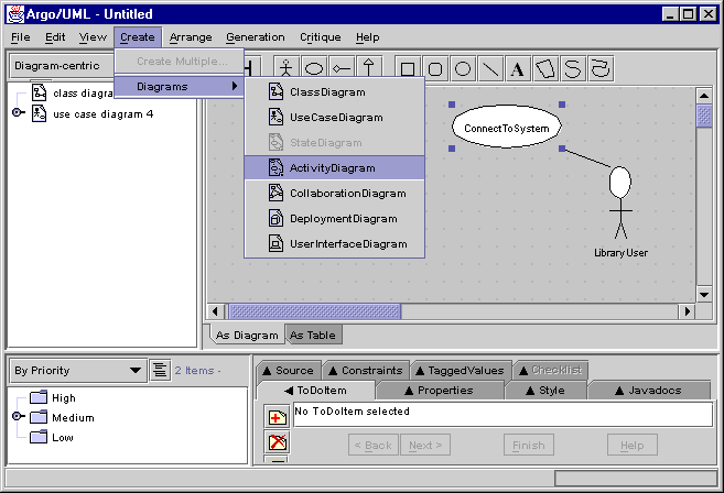
An activity diagram is created by selecting the [create]
> [diagrams] > [activity diagram] option in the ARGOi main
menu. This option, however, is available only when a structural element
of the model has been previously selected. Indeed, this element of the
model provides the context for the activity diagram. For instance, in the
figure below, the activity diagram that is going to be created specifies
the behaviour of the part of the system's functionality represented
by the ConnectToSystem use case.

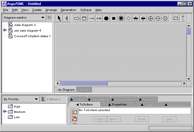
The created activity diagram is presented as an empty workspace, as in the figure below, where the activity diagram constructors are selected, placed, connected and modified in order to specify the behaviour of the ConnectToSystem functionality.

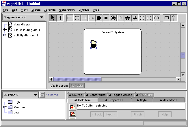
In the following figure, the ConnectToSystem activity was added to the activity diagram. Activity diagrams are built using the constructors available in the activity diagram editor menu. In the following figure the UMLi constructors are shown.

An initial version of the activity diagram describing the behaviour of the ConnectToSystem functionality is presented in the following figure. This figure aims to provide the motivation for modelling the rest of the ConnectToSystem functionality, which is more fully explained in the following sections.
