UMLi
and ARGOi:
A Short Tutorial
1. Introduction
UMLi is a modelling language that extends UML
providing the following additional facilities for user interface design:
-
a new diagram for modelling UI presentations called a user
interface diagram.
-
Each user interface diagram is composed of one FreeContainer
 that is a top-level "window";
-
FreeContainers may contain Containers ,
Editors
,
Displayers
,
Inputters
and ActionInvokers;
-
Displayers
 are responsible for sending visual information to users;
-
Inputters
 are responsible for receiving information from users;
-
Editors
 are simultaneously Displayers and Inputters;
-
ActionInvokers
 are responsible for receiving information from users in the form of events;
-
Containers
 may contain other Containers, Editors, Displayers, Inputters and Action
Invokers;
-
The user interface diagram constructors are InteractionClasses
that are specialised UML Classes. The instance of these InteractiveClasses
are the interaction objects (or widgets).
The following figure presents a user interface diagram for
the ConnectUI where a user connects
to the system proving his/her login and password. Some definitions required
to understand this diagram and some modelling facilities required to build
this diagram are presented in this tutorial.

-
a new set of activity diagram constructors for modelling
UI behaviour:
-
new activity diagram PseudoStates for modelling common UI
behaviour called selection states;
-
new stereotypes for modelling object flows of UI objects.
These stereotypes identify the interaction object flows and they
are responsible for specifying the collaboration:
-
among interaction objects, and
-
between interaction objects and objects from the domain.
The following figure presents a partial view of the activity
diagram for the ConnectUI. Some
definitions required to understand this diagram and some modelling facilities
required to build this diagram are presented in this tutorial.
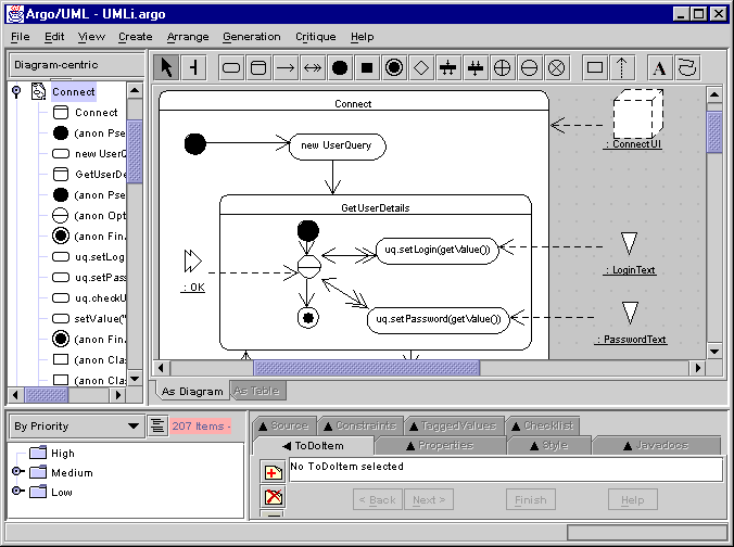
The following screen snapshots in this tutorial may clarify
the purpose of each one of these new constructors on the design of UIs.
These screen snapshots were produced using ARGOi, a design environment
that supports the construction of UMLi models. ARGOi is an
extended version of ArgoUML. ARGOi
is freely available here.
Being a conservative extension of UML, UMLi, in principle, could
be implemented in any UML-based design environment.
If you don't have experience with UML tools, we suggest
a visit to the ArgoUML site, and in particular to its tutorial, to learn
more about a standard UML-based design environment . From there, we suggest
a visit to the rest of this tutorial which is organised as follows.
Concerning the modelling of UI presentations:
Concerning the modelling of UI behaviour:
2. Creating
a user interface diagram
The presentation is the visual part of a user interface.
In UMLi, UI presentations are represented in a conceptual way in
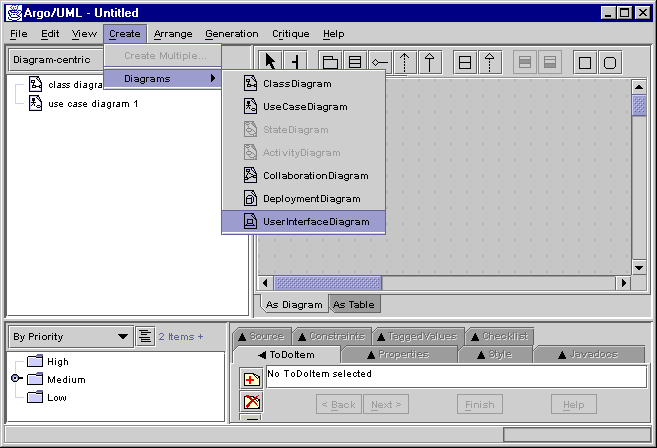
user interface diagrams. The creation of a user interface diagram consists
of selecting the [create] > [diagrams]
> [user interface diagram] option in the main ARGOi menu
as presented in the following figure.
In ARGOi, each user interface diagram contains
one FreeContainer that is created along with the user interface diagram.
FreeContainers model top-level "windows". The following figure presents
a recently created user interface diagram containing a FreeContainer.
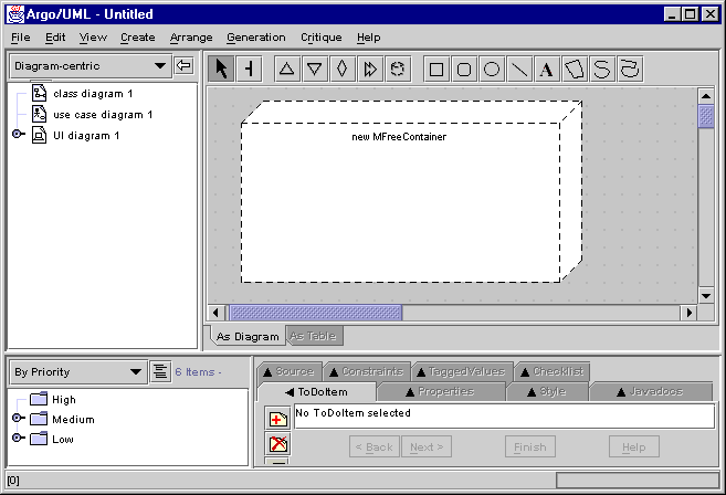
The name of the current user interface diagram (UI diagram
1) and its FreeContainer (new MFreeContainer) can be renamed by selecting
the diagram and the FreeContainer respectively.
Return to the beginning of the tutorial
3.
Adding
new InteractionClasses to a user interface diagram
The selection menu on the user interface diagram editor,
as presented in the following figure, contains a button for each InteractionClass
that can be inserted into the diagram's FreeContainer. FreeContainers are
created along with the user interface diagram.
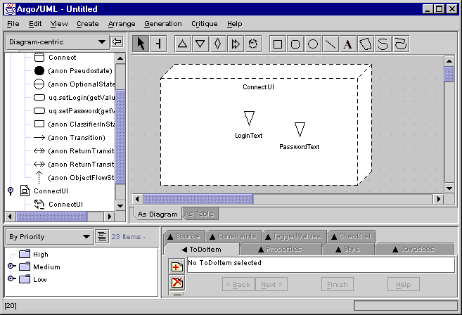
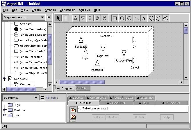
The Inputter, Displayer and Editor are PrimitiveInteractionClasses.
These are the constructors that identify how interactive systems can receive
and send data from/to users. In the following figure an early version of
the ConnectUI FreeContainer is
presented where only the LoginText
and PasswordText Inputters are
specified.
ActionInvokers are mainly used to trigger and/or confirm
actions that users can perform. The elicitation and modelling of ActionInvokers
often occurs along with the modelling of behavioural diagrams, i.e., activity
diagrams and sequence diagrams. In the following figure it can be observed
that the OK and Cancel
ActionInvokers were added to the model in the same way as other PrimitiveInteractionClasses
such as the Feedback Displayer.
The Container is used to logically organise user interface
diagrams by grouping InteractionClasses within FreeContainers as in the
following figure.
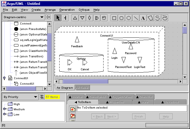
User interfaces specified in user interface diagrams are
conceptual models of UI presentations since they specify just abstract
aspects of user interfaces that may be relevant to understand the UI. For
example, the ConnectUI FreeContainer
in the figure above does not say anything about things such as:
-
layout (for instance, whether the Login
Displayer is going to be at the left or the right of the LoginText,
or whether the UserDetailsCN is
going to be to the top, the left, the right or the bottom of the the ConnectUI);
-
widget selection (for instance, if the OK
ActionInvoker is going to be a button, a list, a combo box, etc.);
-
toolkits and programming language.
Return to the beginning of the tutorial
4. Creating
an activity diagram
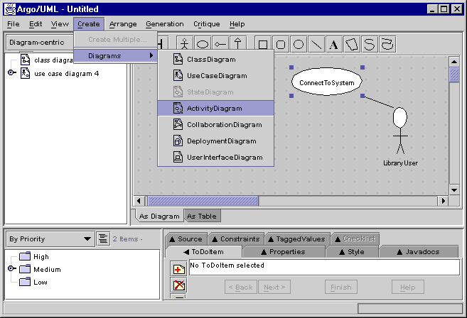
An activity diagram is created by selecting the [create]
> [diagrams] > [activity diagram] option in the ARGOi main
menu. This option, however, is available only when a structural element
of the model has been previously selected. Indeed, this element of the
model provides the context for the activity diagram. For instance, in the
figure below, the activity diagram that is going to be created specifies
the behaviour of the part of the system's functionality represented
by the ConnectToSystem use case.
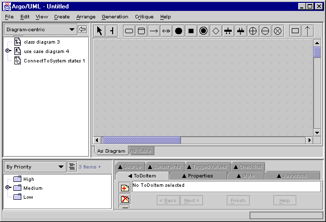
The created activity diagram is presented as an empty
workspace, as in the figure below, where the activity diagram constructors
are selected, placed, connected and modified in order to specify the behaviour
of the ConnectToSystem functionality.
In the following figure, the ConnectToSystem
activity was added to the activity diagram. Activity diagrams are built
using the constructors available in the activity diagram editor menu. In
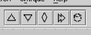
the following figure the UMLi constructors are shown.

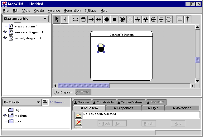
An initial version of the activity diagram describing
the behaviour of the ConnectToSystem
functionality is presented in the following figure. This figure aims to
provide the motivation for modelling the rest of the ConnectToSystem
functionality, which is more fully explained in the following sections.
Return to the beginning of the tutorial
5. Creating
a SelectionState
5.1. Categories of SelectionState
SelectionStates are added to activity diagrams
by selecting one of them from the activity diagram menu. UMLi specifies
three categories of SelectionStates:
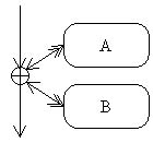
OrderIndependentState: A and B in the following
figure are the selectable activities of the SelectionState. There, every
selectable activity should be executed once during the performance of the
selection state. However they can be performed in any order according to
the users selection. An OrderIndependentState must have at least two selectable
activities.
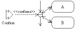
OptionalState: In this category of SelectionState,
users can select the execution of any selectable activity any number of
times, including none. In this case, a <<confirms>>
interaction object flow must be specified in order to allow users to
finish the selection state. An OptionalState must have at least two selectable
activities.
RepeatableState: In this category of SelectionState,
a selectable activity is continuously performed while the selection state
is not finished by a user using the mandatory <<cancels>>
interaction object flow that is specified along with the RepeatableState.
A RepeatableState must have one selectable activity only.
5.2. Creating SelectionStates
STEP 1: Add the desired SelectionState to the
activity diagram.
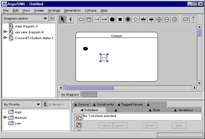
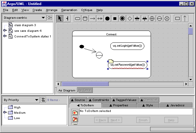
STEP 2: Create the selectable activities (that
can be activities or action states). If the SelectionState is an OrderIndependentState
or an OptionalState it should have at least two selectable activities.
If the SelectionState is a RepeatableState it should have only one selectable
state.
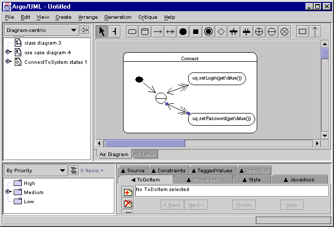
STEP 3: Create ReturnTransitions FROM the
SelectionState TO its selectable states.
Return to the beginning of the tutorial
6. Creating interaction object flows
6.1. Object Flows
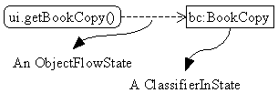
An object flow is composed of two UML constructors:
the
ClassifierInState, that is the object itself, and the ObjectFlowState
that is the arrow connecting a ClassifierInState to an ActionState. The
graphical notation of ClassifierInState and ObjectFlowState can be better
understood in the following figure.
In UMLi, in addition to ActionStates,
ClassifierInStates that are of type InteractionClasses can also be associated
with Activities and SelectionStates.
6.2. Creating Object Flows
The following method describes how to create object
flows in ARGOi. An interaction object flow is a particular case
that is described by the same method.
STEP 1. Create a ClassifierInState.
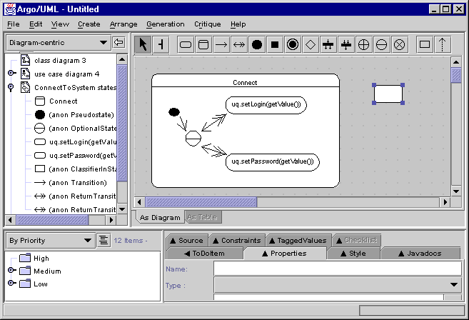
STEP 2. Give a type to the ClassifierInState:
The type (that is any one of the classes actually specified in the model)
of the selected ClassifierInState can be specified in the form identified
by the Properties tab in the following
figure. In fact, any additional properties (including any that may not
have a graphical notation) can be specified in ARGOi for the current
selected element in the model by using the Properties
tab.

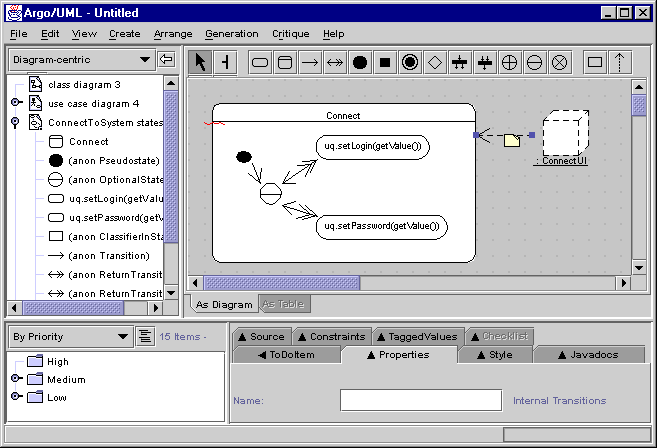
If the selected type is an InteractionClass then the graphical
notation of the ClassifierInState is its notation in the user interface
diagram. For instance, in the figure in STEP 3, the ClassifierInState of
type ConnectUI (that is a FreeContainer),
is graphically replaced by a FreeContainer.
STEP 3. Relate a ClassifierInState to an Activity,
ActionState
or
SelectionState.
ObjectFlowStates are used to specify how ClassifierInStates are used by
activities and action states.
6.3. Interaction Object Flows
A <<presents>>
interaction object flow often connects a FreeContainer to an activity.
It can also connect a FreeContainer to an ActionState. In both cases, this
category of object flow represents the process of instantiating and making
visible the FreeContainer and its InteractionClasses when the system control
flow reaches the associated activity or action state, and the process of
making invisible and destroying the FreeContainer and its InteractionClasses
when the system control flow leaves the activity or action state.
A <<interacts>>
interaction object flow connects a PrimitiveInteractionClass or an
ActionInvoker to an action state. It can also connect a Container to a
selection state. This category of object flow represents the process of
enabling for interaction the InteractionClass when the system control flow
reaches the associated activity, action state or selection state, and the
process of disabling for interaction the InteractionClass when the system
control flow leaves the activity, action state or selection state.
A <<cancels>> interaction
object flow connects an ActionInvoker to an activity or selection state.
In both cases, this category of object flow represents the cancelling of
the associated activity or selection state by interacting with the ActionInvoker.
A <<confirms>> interaction
object flow connects an ActionInvoker to an OptionalState. It normally
finishes the OptionalState.
A <<activates>>
interaction object flow connects an ActionInvoker to an activity or
action state. It triggers the execution of the activity or action state
by interacting with the ActionInvoker.
6.4. Final Message
This is the end of this short tutorial. Further details
concerning the specification of the UMLi notation and the ARGOi
tool are available in the UMLi
publications. The authors of UMLi and ARGOi (see the
UMLi
personnel) would be glad to know what you think about UMLi
and ARGOi. Thus, please let us know your opinion about our product
sending an e-mail to paulo@psemantica.com.
Return to the beginning of the tutorial
 that is a top-level "window";
 are responsible for sending visual information to users;
 are responsible for receiving information from users;
 are simultaneously Displayers and Inputters;
 are responsible for receiving information from users in the form of events;
 may contain other Containers, Editors, Displayers, Inputters and Action
Invokers;


